
Segment displays: turn a character into a wiring plan
Use a Seven Segment Display and 7 Segment Converter for digits. For an OPEN sign, letters or a dollar symbol, pair a Fourteen Segment Display with a 14 Segment Converter.
The number you feed into the converter is not always the character on the screen. On the 14-segment converter, 10 produces 0, 11 produces A and 45 produces $. The planner gives every input’s ON/OFF setting.
Plan your character or sign, then keep the converter inputs accessible while building.

Choose a character. Get its input plan.
One character per display and matching converter. ON means a steady signal at that converter input; every other input stays OFF.
Use digits 0–9. Spaces have no input plan here; leave a physical gap between words.
1 display planned. Each row below is a separate converter.
If ports are outside the view, swipe the table sideways.
| Target | Code | A 1 | B 2 | C 4 | D 8 |
|---|---|---|---|---|---|
| 1. 7 | 7 | ON | ON | ON | OFF |
Read the weights, then add the ON inputs
1 + 2 + 4 = 7. Target: 7.
This is a code diagram, not the physical position of sockets. Follow the converter’s A–D input labels.
Budget a separate-input test board
Each wired input gets its own lever and one Basic Wire. The converter sits behind the display, so this estimate adds no wires between that pair.
Unchecked: buy controls only for this target’s ON inputs. The other ports are left unpowered. This is a test-board budget, not a minimum-cost single-lever shop sign.
- 1 display + 1 converter
- $4,700
- 4 levers + 4 wires
- $2,900
- Parts total
- $7,600
Per part: display $3,500, converter $1,200, lever $520, Basic Wire $205. Excludes ferry travel, mounting wood, spare parts, longer cable runs and switching circuits.
The display lights segments; the converter decodes a value
| Part | What its inputs do | Use it for |
|---|---|---|
| Seven Segment Display | Seven rear inputs light seven individual lines on the front. | A digit, or a manually wired shape. |
| 7 Segment Converter | Four inputs A–D have weights 1, 2, 4, 8. | Turning a single decimal digit into segment signals. |
| Fourteen Segment Display | Fourteen rear inputs light individual lines. | Letters and more detailed shapes. |
| 14 Segment Converter | Six inputs A–F have weights 1, 2, 4, 8, 16, 32. | Turning a character code into segment signals. |
The converter is optional when powering individual display segments by hand. It is the useful part when you want to choose a whole digit or letter from a code. Connect your controls to the converter inputs, not to arbitrary sockets on the display.
Wire one character before building the whole sign
- Buy the display and its matching converter at Link’s Logic. A 7-segment converter and a 14-segment converter use different input plans.
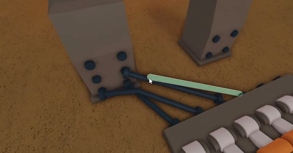
- Place the converter directly behind the display with its outputs facing the display’s rear inputs. Leave room to reach the converter sockets. A displaced converter needs output wires to the corresponding display inputs.
- Use separate levers and wires for a small test board. Connect each lever to one converter input. A lever holds its signal; a button only pulses. Start with every lever OFF.
- Choose the target in the planner. Turn ON only the listed inputs and leave the rest OFF. For 7 on a 7-segment pair, A, B and C are ON, D is OFF.
- Check the front before hiding the wires. For A on a 14-segment pair, use A, B and D: 1 + 2 + 8 = 11. The converter’s port A and the displayed letter A are different things.
Basic Wire is dark when unpowered and blue when powered. If the output is wrong, compare every input with the plan, including the ones that should be OFF. For example, 6 needs B and C; an extra active A changes the sum to 7. For signal direction and joined wires, use the logic and wires guide.

Why does zero need different inputs?
A 7-segment converter takes the digit value itself: 0 means all four inputs OFF. A 14-segment converter uses its character table: 0 has code 10, so B (2) and D (8) are ON. Reusing the same input pattern across the two converter types can produce the wrong character.
Keep the 7-segment planner to digits 0–9. One display is one character: 73 needs two display/converter pairs, with separate inputs for 7 and 3. The 14-segment planner uses the custom table below, not ASCII numbers.
14-segment character codes
Digits 1–9 use codes 1–9; 0 uses 10. Letters A–Z occupy 11–36. Select a character in the planner to split its code into A–F input settings.
Open the complete character table
| Character | Code | ON input weights |
|---|---|---|
| 1 | 1 | 1 |
| 2 | 2 | 2 |
| 3 | 3 | 1 + 2 |
| 4 | 4 | 4 |
| 5 | 5 | 1 + 4 |
| 6 | 6 | 2 + 4 |
| 7 | 7 | 1 + 2 + 4 |
| 8 | 8 | 8 |
| 9 | 9 | 1 + 8 |
| 0 | 10 | 2 + 8 |
| A | 11 | 1 + 2 + 8 |
| B | 12 | 4 + 8 |
| C | 13 | 1 + 4 + 8 |
| D | 14 | 2 + 4 + 8 |
| E | 15 | 1 + 2 + 4 + 8 |
| F | 16 | 16 |
| G | 17 | 1 + 16 |
| H | 18 | 2 + 16 |
| I | 19 | 1 + 2 + 16 |
| J | 20 | 4 + 16 |
| K | 21 | 1 + 4 + 16 |
| L | 22 | 2 + 4 + 16 |
| M | 23 | 1 + 2 + 4 + 16 |
| N | 24 | 8 + 16 |
| O | 25 | 1 + 8 + 16 |
| P | 26 | 2 + 8 + 16 |
| Q | 27 | 1 + 2 + 8 + 16 |
| R | 28 | 4 + 8 + 16 |
| S | 29 | 1 + 4 + 8 + 16 |
| T | 30 | 2 + 4 + 8 + 16 |
| U | 31 | 1 + 2 + 4 + 8 + 16 |
| V | 32 | 32 |
| W | 33 | 1 + 32 |
| X | 34 | 2 + 32 |
| Y | 35 | 1 + 2 + 32 |
| Z | 36 | 4 + 32 |
| + | 37 | 1 + 4 + 32 |
| - | 38 | 2 + 4 + 32 |
| / | 39 | 1 + 2 + 4 + 32 |
| \ | 40 | 8 + 32 |
| ( | 41 | 1 + 8 + 32 |
| ) | 42 | 2 + 8 + 32 |
| ? | 43 | 1 + 2 + 8 + 32 |
| * | 44 | 4 + 8 + 32 |
| $ | 45 | 1 + 4 + 8 + 32 |
| & | 46 | 2 + 4 + 8 + 32 |
| % | 47 | 1 + 2 + 4 + 8 + 32 |
| ^ | 48 | 16 + 32 |
| " | 49 | 1 + 16 + 32 |
| ' | 50 | 2 + 16 + 32 |
| ` | 51 | 1 + 2 + 16 + 32 |
The planner has no mapping for spaces, punctuation outside this table, or code values above 51. For a space in a shop sign, leave a gap between displays.
Can one lever control an OPEN sign?
For fixed text, one common signal can feed the selected ON inputs across several converters. It cannot independently change those letters: every connected input follows the same lever. Keep the intended OFF inputs out of that common line.
Start by making each letter work with separate controls. OPEN needs codes 25, 26, 15 and 24 on four 14-segment converters. The planner’s test-board budget deliberately keeps those inputs separate; a shared lever and branched wiring use a different parts list. Switching between OPEN and CLOSED adds a second input pattern and a switching circuit, beyond this static character plan.
If a correct plan still gives the wrong result
Isolate one converter/display pair and one input at a time. Remove shared feeds, check the converter type, inspect the attachment behind the screen and compare the lit wires with the intended weights. A code plan describes the requested inputs; it does not simulate server behaviour or repair a faulty component.
Keep your saved slot before expanding the build. After reloading, inspect the actual connections again before copying the layout across a long sign. Use the map and ferry guide for Link’s Logic, and the wood value calculator to plan how much lumber to sell for the parts.